And it all came unhinged :)
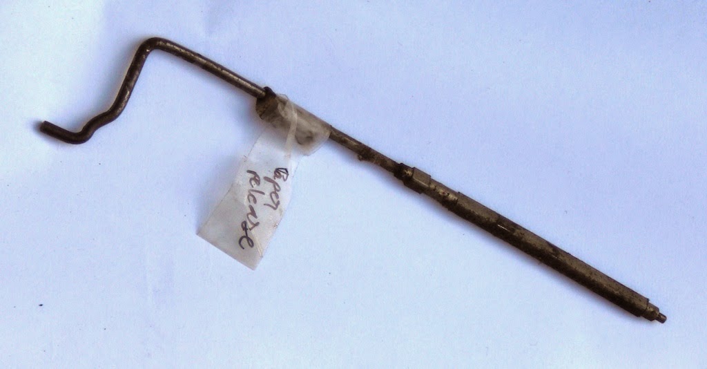
Well, not quite that bad, but there were a few parts that could have been left on. The two screws at the back of the carriage hold the bracket of the paper release lever. Removing those screws yields the paper release lever and rod.
![]()
Didn't have to come off, but will be able to give it a good clean now.
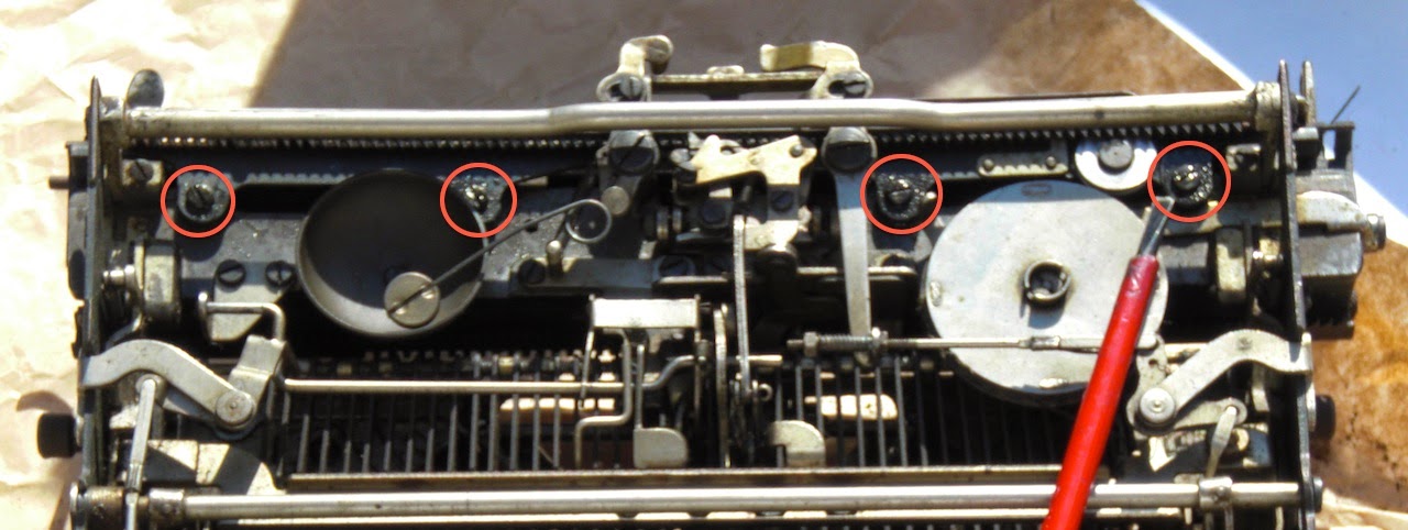
Having looked at the way it seems to be put together, started off by trying to loosen the carriage bearings to see if that would allow it to come off. The rear bearing rail is held by the four screws circled in the picture. Just loosening these a turn, the carriage bearing can be adjusted. These were very solid, took oil and a few taps with a small hammer to loosen them.
![]()
This does give the carriage play, but does not allow it to come off. If the carriage goes sluggish or blocks somewhere along its travel, adjusting such a rail may help. Maybe not necessary to loosen this when sliding off the carriage, but will make it easier to slide off and on again.
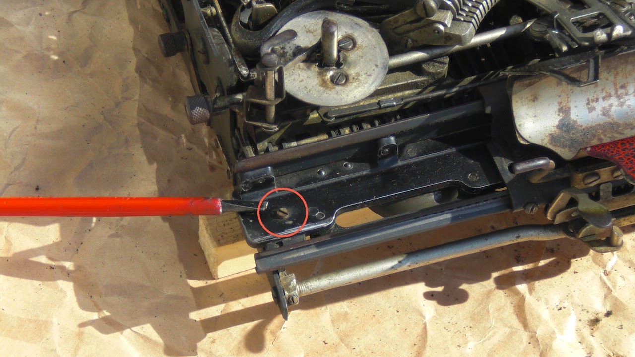
Spending some more time to look at where the carriage is held revealed a painfully obvious stop-screw in plain sight. On both ends of the carriage base that is fixed to the machine there is a small stop-screw. These screws stop a small stud in the centre bottom of the moving carriage base.
![]()
A bit embarrassed, removed that screw and the carriage slides off easily revealing the two sets of bearings. The front and rear bearings are held nicely in a cage with a sprocket that ensures they stay in situ.
![]()
With the carriage off, it becomes more practical to finally get at the feed rollers. Looking more closely again at the paper-tray, this is impossible to remove by unscrewing the brackets. The paper tray is right on top of the screws that hold the brackets to the carriage base. As far as I can tell the only way this can have been assembled is by holding it all down in a jig and then insert the rod in the hinge. (Moments to wish a typewriter repair shop was nearby. Or even not-nearby for that matter :-)
Oh, the two screws underneath the centre of the carriage base hold a small cast block that holds the spring wires that provide the clamping force for the feed rollers. (These also did not have to be loosened... Oh well, discoveries.)
With better access, it is however possible to carefully bend open a little the folded lips that hold the feed roller axles. With the eyelet lips bent open just a bit it becomes possible to use pliers to pull out the rods and get at the rollers.
![]()
To keep them in, one end of the rods is knurled. This knurled end is press-fitted into its lip during assembly to keep it in place firm. The front feed-roller rods were applied from the outsides, so can be pulled outward. The rear feed-roller rods (in the bogies) are identical sub assemblies that were probably fitted to the carriage already assembled. So the left rear rod should have been pulled to the right and not left through the rollers...
Got them all out now to be made round again. Most rusted parts of the carriage are now also accessible to give them a good clean and shine.
Progress :-)
Well, not quite that bad, but there were a few parts that could have been left on. The two screws at the back of the carriage hold the bracket of the paper release lever. Removing those screws yields the paper release lever and rod.
Didn't have to come off, but will be able to give it a good clean now.
Having looked at the way it seems to be put together, started off by trying to loosen the carriage bearings to see if that would allow it to come off. The rear bearing rail is held by the four screws circled in the picture. Just loosening these a turn, the carriage bearing can be adjusted. These were very solid, took oil and a few taps with a small hammer to loosen them.
This does give the carriage play, but does not allow it to come off. If the carriage goes sluggish or blocks somewhere along its travel, adjusting such a rail may help. Maybe not necessary to loosen this when sliding off the carriage, but will make it easier to slide off and on again.
Spending some more time to look at where the carriage is held revealed a painfully obvious stop-screw in plain sight. On both ends of the carriage base that is fixed to the machine there is a small stop-screw. These screws stop a small stud in the centre bottom of the moving carriage base.
A bit embarrassed, removed that screw and the carriage slides off easily revealing the two sets of bearings. The front and rear bearings are held nicely in a cage with a sprocket that ensures they stay in situ.

With the carriage off, it becomes more practical to finally get at the feed rollers. Looking more closely again at the paper-tray, this is impossible to remove by unscrewing the brackets. The paper tray is right on top of the screws that hold the brackets to the carriage base. As far as I can tell the only way this can have been assembled is by holding it all down in a jig and then insert the rod in the hinge. (Moments to wish a typewriter repair shop was nearby. Or even not-nearby for that matter :-)
Oh, the two screws underneath the centre of the carriage base hold a small cast block that holds the spring wires that provide the clamping force for the feed rollers. (These also did not have to be loosened... Oh well, discoveries.)
With better access, it is however possible to carefully bend open a little the folded lips that hold the feed roller axles. With the eyelet lips bent open just a bit it becomes possible to use pliers to pull out the rods and get at the rollers.

To keep them in, one end of the rods is knurled. This knurled end is press-fitted into its lip during assembly to keep it in place firm. The front feed-roller rods were applied from the outsides, so can be pulled outward. The rear feed-roller rods (in the bogies) are identical sub assemblies that were probably fitted to the carriage already assembled. So the left rear rod should have been pulled to the right and not left through the rollers...
Got them all out now to be made round again. Most rusted parts of the carriage are now also accessible to give them a good clean and shine.
Progress :-)


