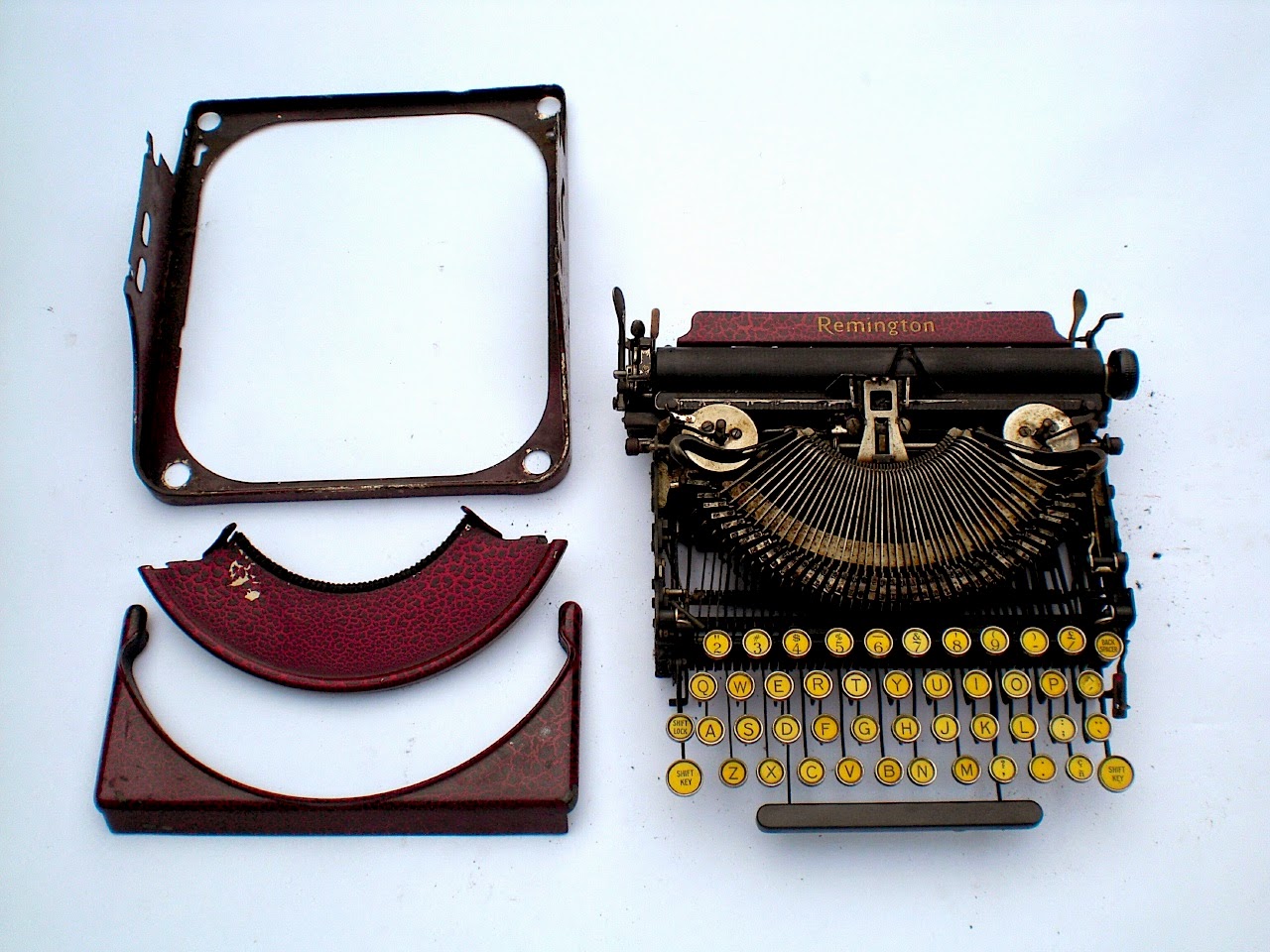
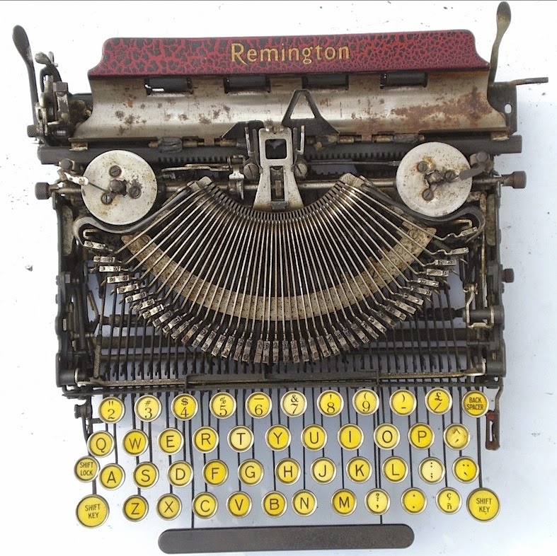
Next to re-covering a leathercloth case, nickel plating was a new activity to gain experience on.
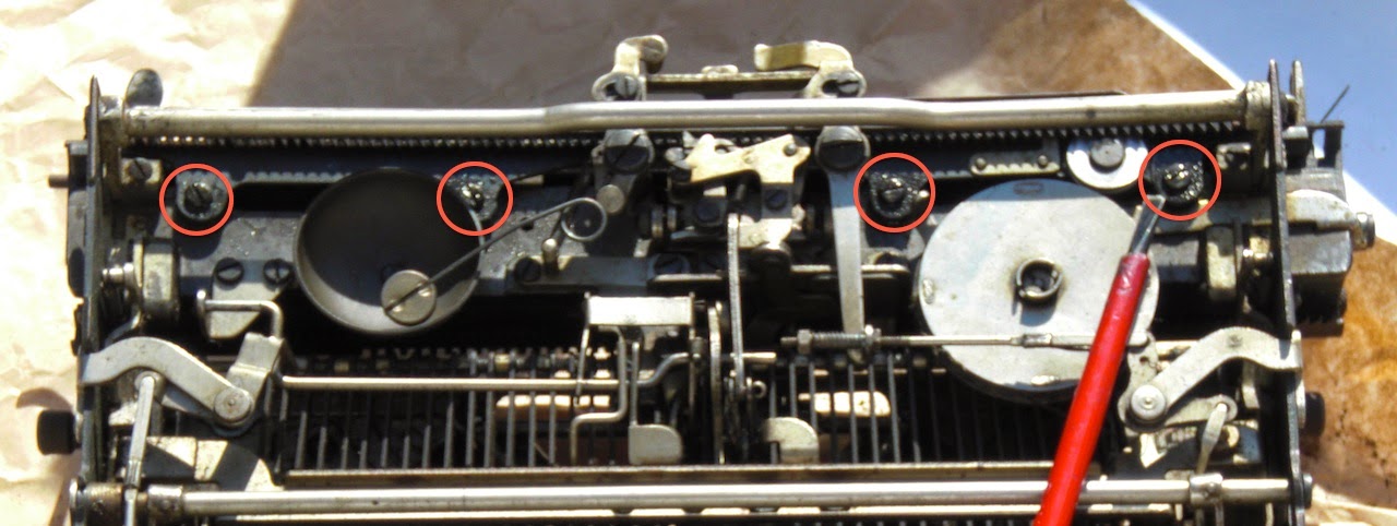
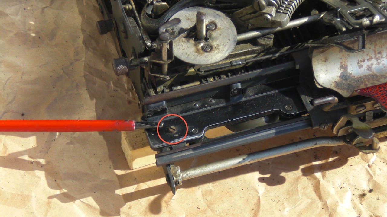
Older machines mostly don't have chrome, but nickel plating for the shiny parts. (Chrome plating became viable industrially I believe around '26.) Some of the fittings and screws of the 101 were a bit rusty, some of the screws more than a bit. To bring back some shine to these parts also, they were re-plated.
![]()
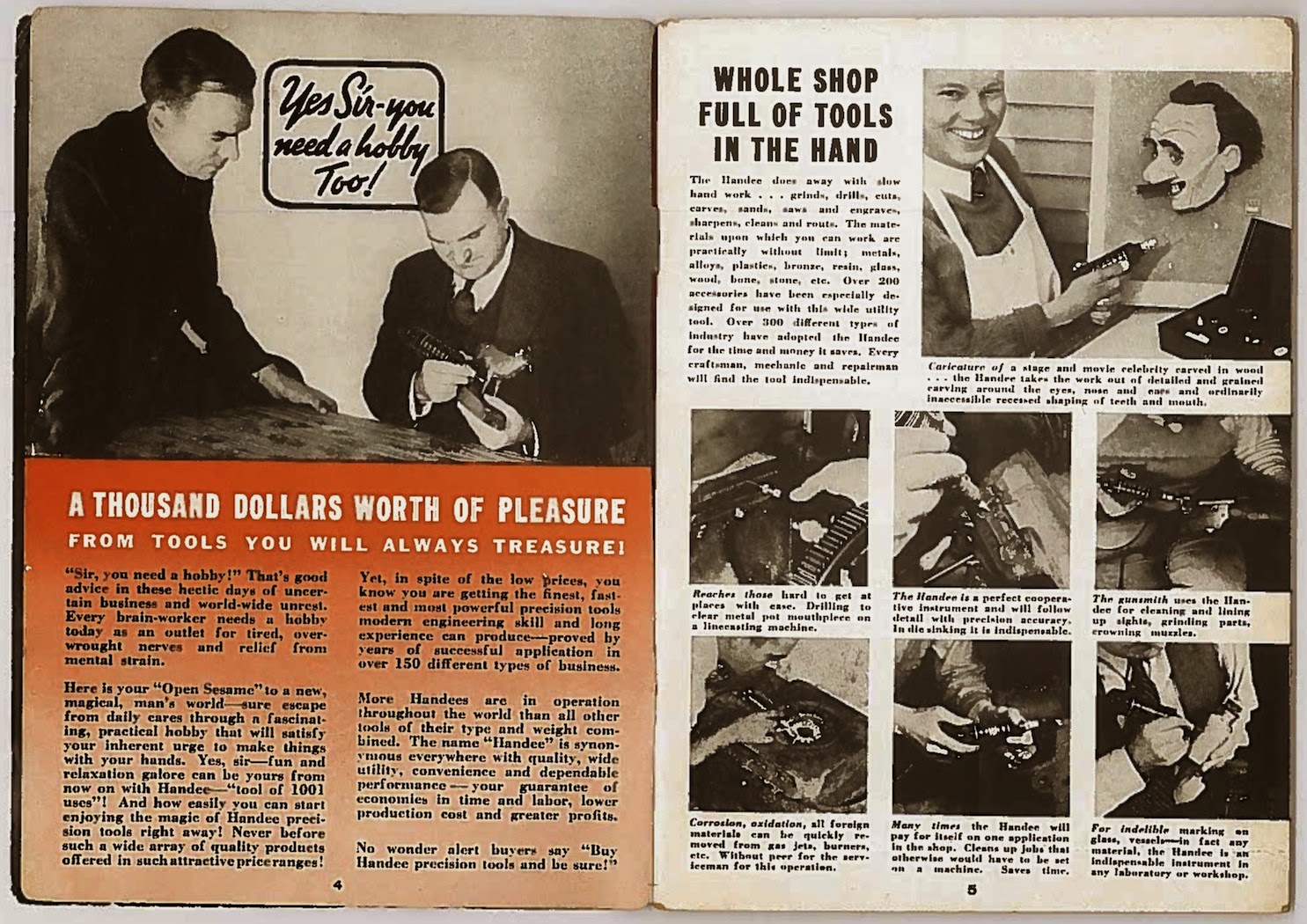
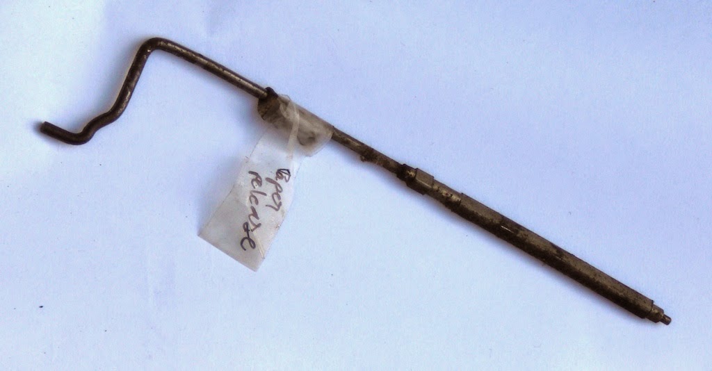
Several sites on the internet describe how to do electroplating and shops offer for sale solutions or kits to do nickel plating. From some online hints on plating, however decided to do electroplating entirely with regular home and kitchen ingredients. These rusted fittings for the carrying handle ('pakawa') were badly pitted, but even then were improved by the process. (Chemical de-rusting would perhaps have been better.)
![]()
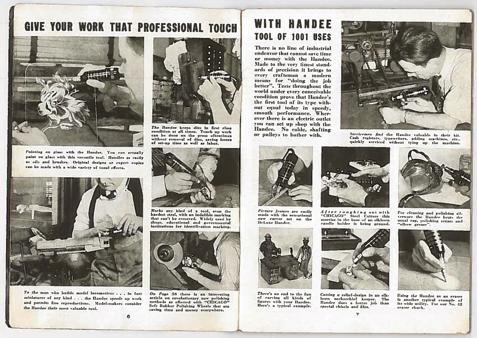
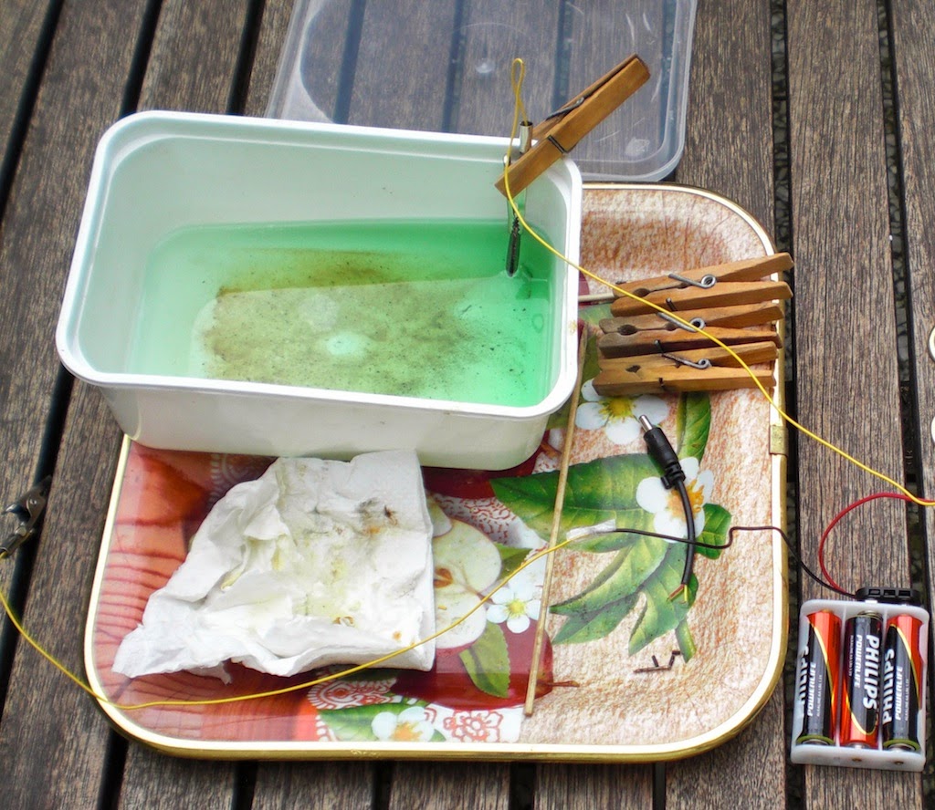
This electrolyte was mixed from kitchen ingredients; vinegar, salt and sugar. For nickel an old coin was found, a battery for the electricity.
Measure what is the smallest amount of liquid that can be used to fill the chosen container. The smallest amount that enables the parts to be submerged to be plated. In this case a plastic take-away container with a lid was used. A lid is good to have, to be able to close the electro-plating bath for storage.
Using the kitchen scale, find out how much volume (weight) this was. For every milliliter of vinegar, add a tenth of that in salt and in sugar. So e.g. 200 ml (or 200 gram) of vinegar, add 20 grams of salt and 20 grams of sugar. (Use powdered sugar for easy dissolving.)
It helps to have heated the vinegar a bit to around 50 degree C, the salt and sugar dissolves easier then.
Regular vinegar, without any 'taste' elements if possible. You only want the acidity and no complex molecules or organic stuff in there to complicate the reactions in the mixture. The salt helps making it conductive to electricity, plain kitchen salt (NaCl).
But then the sugar. Why add sugar. Did some head-scratching with a chemistry colleague about why sugar would be good to include, but it probably makes sense. The sugar does not electrolyze, does not take part in the reactions. The sugar does however go into solution, so adds to the saturation of the electrolyte. This means that less of the nickel-salts need to be put into the solution before the plating at the cathode starts. It makes the plating channel more efficient.
So far, the mixture is still safe; it probably tastes very bad, but is not unhealthy as such. Note that as soon as you start plating with the electrodes in the mixture, you are creating chemical waste. This will contain metal salts and will need to be disposed of safely through the chemical waste disposal route of the local municipality. This is another reason to use the smallest amount of electrolyte that will do the job.
For the electricity, used a battery. A voltage of between 3 and 5 volts should be fine on this scale. Also tried a 9V battery, but that was too much. Too high a current (battery overheats due to internal resistance) and too rough a plating (porous).
Using alligator clips, the coin is attached to the '+' of the battery and a to-be-plated part to the '-' of the battery. For the nickel-supplying electrode an old coin was used. Actual nickel coins are not as common as they were, but this old 'gulden' is actually made almost completely of nickel. Of course the coin (or other nickel metal part you use) will partly dissolve and not survive.
It's a good idea to do this in a well ventilated area. Not only because of the chemical waste being created in the electro-plating bath (unhealthy stuff), also because hydrogen and oxygen will be created at the electrodes.
As soon as the electric circuit is closed, bubbles appear at the electrodes and soon a green haze will form around the positive electrode. That is the nickel salts in the solution. First the electrolyte mixture needs to be sufficiently filled with nickel salts for these to reach the negative electrode, but then the nickel is deposited on the to be plated parts. With a saturated mixture, it now takes between 10 seconds and a minute to properly nickel-plate a small part. Move around or stir (wooden spoon) a bit to get all surfaces treated. Being able to put a lid on it, the whole electro-lating setup can be put away for a couple of days in between use. Having it all on a tray made sense, as well as some tissue to dry and clean the parts as they come out of the bath.
![]()
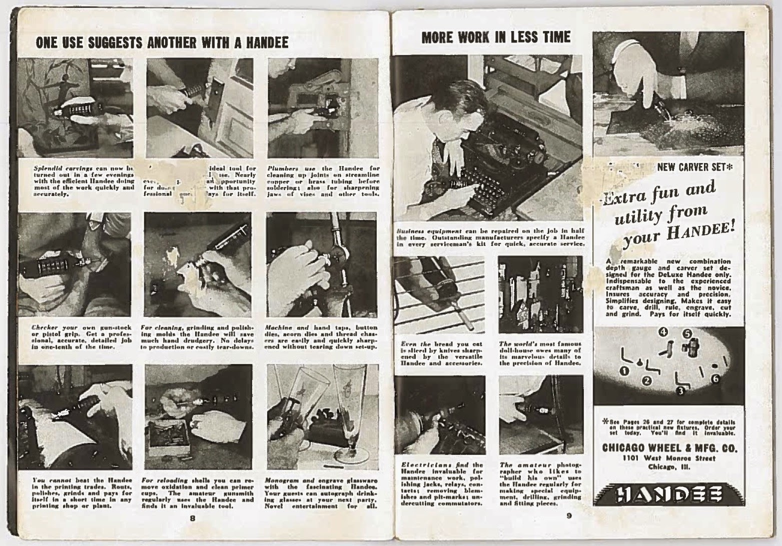
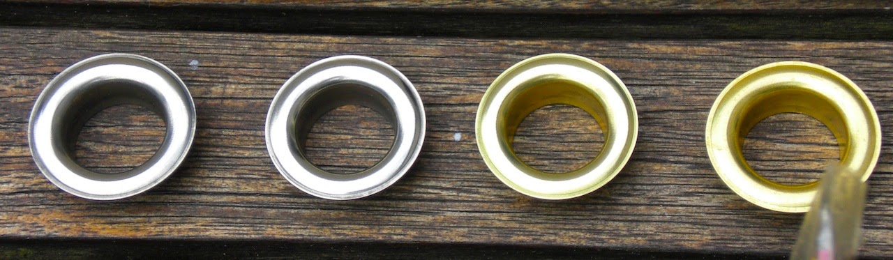
Probably obvious to the experts in this field, but brass or copper parts are really best for plating. The parts do need to be completely clean. That means that also new, brass screws need to be polished to remove 'patina' and any remaining oil or grease from the manufacturing process. Brasso and a soft cloth. Brass rings, the left two already nickel-plated.
![]()
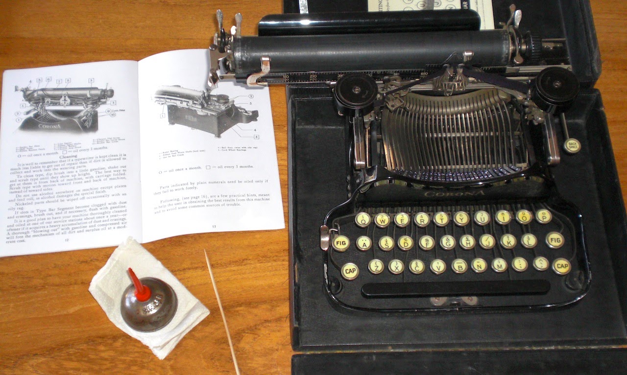
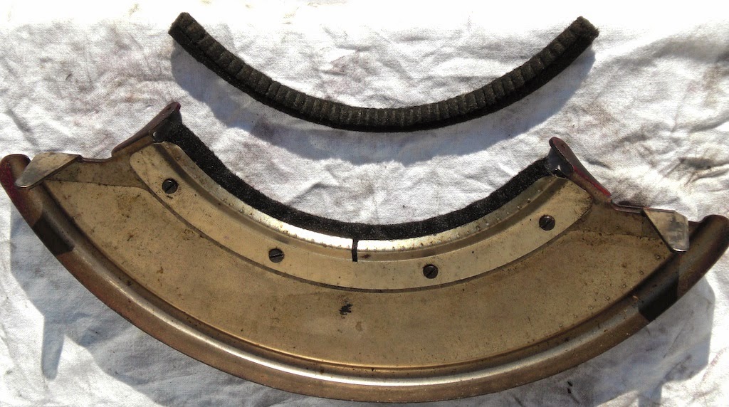
One of the newly nickel plated rings mounted in the new, replacement record storage tray in the lid.
![]()
Having now seen the difference between plain steel and copper (brass) for plating, perhaps a first step of copper plating a part makes sense. For the next project perhaps.
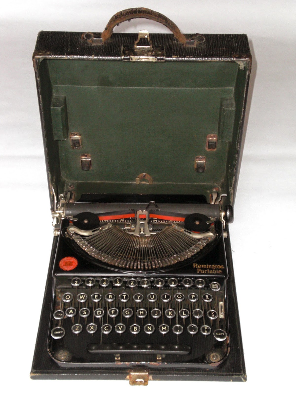
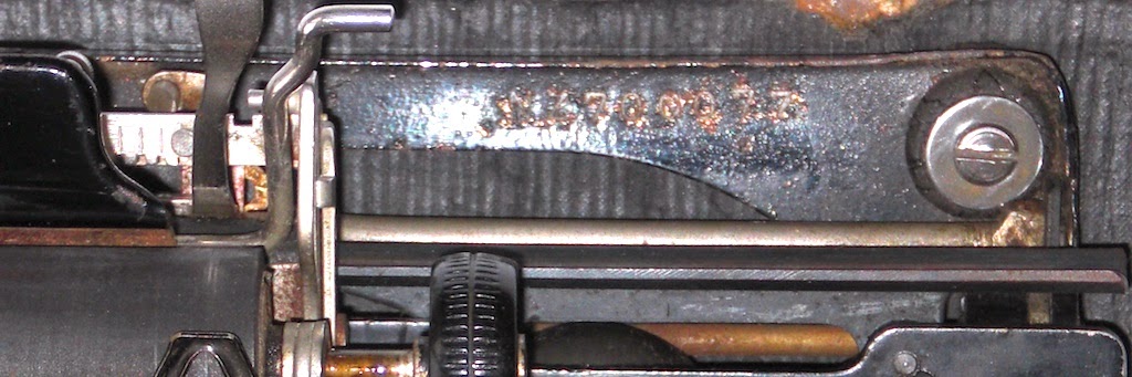
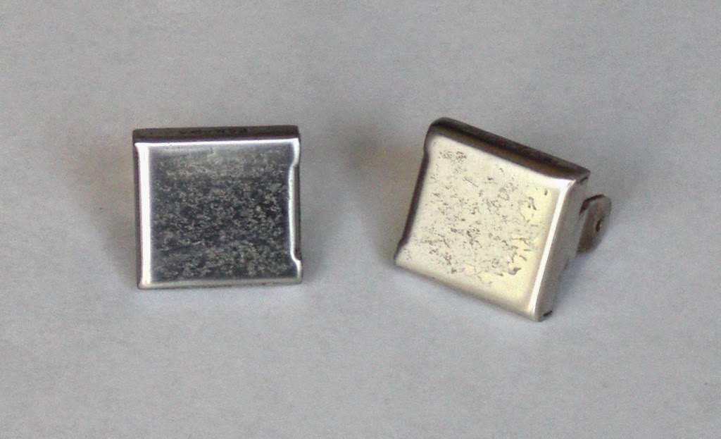
Some screws will probably get a second treatment, but this carrying handle will stay put for a while and will just have to do. (Taking that off requires pretty much a complete disassembly of the whole machine.)
![]()
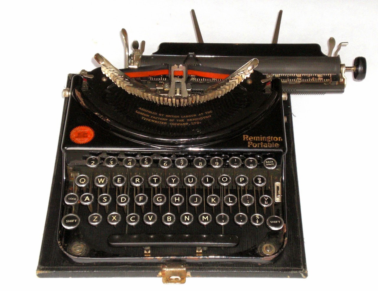
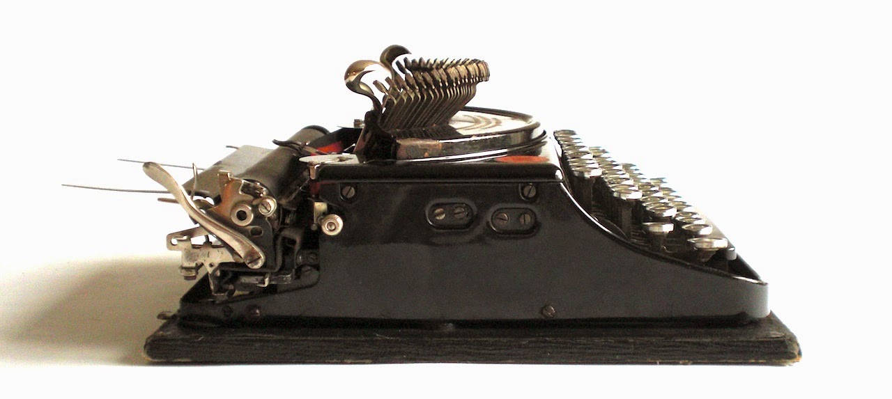
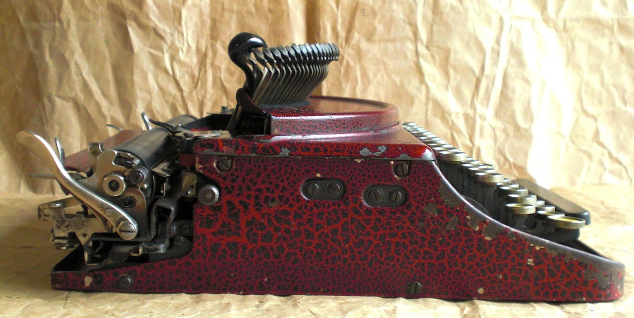
It does look the part though, very flashy deluxe late twenties machine :)
Older machines mostly don't have chrome, but nickel plating for the shiny parts. (Chrome plating became viable industrially I believe around '26.) Some of the fittings and screws of the 101 were a bit rusty, some of the screws more than a bit. To bring back some shine to these parts also, they were re-plated.
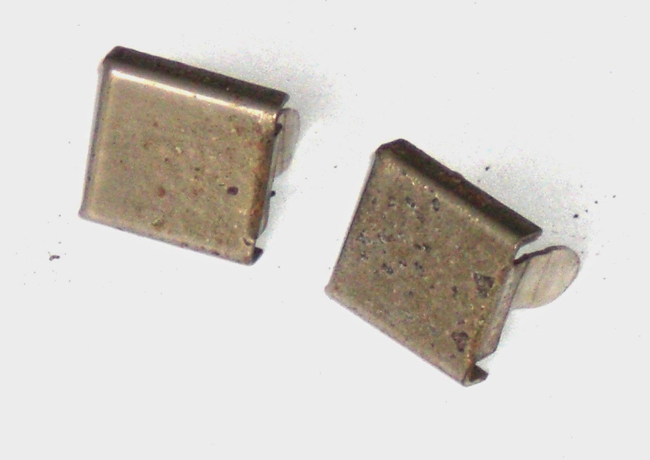
Several sites on the internet describe how to do electroplating and shops offer for sale solutions or kits to do nickel plating. From some online hints on plating, however decided to do electroplating entirely with regular home and kitchen ingredients. These rusted fittings for the carrying handle ('pakawa') were badly pitted, but even then were improved by the process. (Chemical de-rusting would perhaps have been better.)
This electrolyte was mixed from kitchen ingredients; vinegar, salt and sugar. For nickel an old coin was found, a battery for the electricity.
Measure what is the smallest amount of liquid that can be used to fill the chosen container. The smallest amount that enables the parts to be submerged to be plated. In this case a plastic take-away container with a lid was used. A lid is good to have, to be able to close the electro-plating bath for storage.
Using the kitchen scale, find out how much volume (weight) this was. For every milliliter of vinegar, add a tenth of that in salt and in sugar. So e.g. 200 ml (or 200 gram) of vinegar, add 20 grams of salt and 20 grams of sugar. (Use powdered sugar for easy dissolving.)
It helps to have heated the vinegar a bit to around 50 degree C, the salt and sugar dissolves easier then.
Regular vinegar, without any 'taste' elements if possible. You only want the acidity and no complex molecules or organic stuff in there to complicate the reactions in the mixture. The salt helps making it conductive to electricity, plain kitchen salt (NaCl).
But then the sugar. Why add sugar. Did some head-scratching with a chemistry colleague about why sugar would be good to include, but it probably makes sense. The sugar does not electrolyze, does not take part in the reactions. The sugar does however go into solution, so adds to the saturation of the electrolyte. This means that less of the nickel-salts need to be put into the solution before the plating at the cathode starts. It makes the plating channel more efficient.
So far, the mixture is still safe; it probably tastes very bad, but is not unhealthy as such. Note that as soon as you start plating with the electrodes in the mixture, you are creating chemical waste. This will contain metal salts and will need to be disposed of safely through the chemical waste disposal route of the local municipality. This is another reason to use the smallest amount of electrolyte that will do the job.
For the electricity, used a battery. A voltage of between 3 and 5 volts should be fine on this scale. Also tried a 9V battery, but that was too much. Too high a current (battery overheats due to internal resistance) and too rough a plating (porous).
Using alligator clips, the coin is attached to the '+' of the battery and a to-be-plated part to the '-' of the battery. For the nickel-supplying electrode an old coin was used. Actual nickel coins are not as common as they were, but this old 'gulden' is actually made almost completely of nickel. Of course the coin (or other nickel metal part you use) will partly dissolve and not survive.
It's a good idea to do this in a well ventilated area. Not only because of the chemical waste being created in the electro-plating bath (unhealthy stuff), also because hydrogen and oxygen will be created at the electrodes.
Probably obvious to the experts in this field, but brass or copper parts are really best for plating. The parts do need to be completely clean. That means that also new, brass screws need to be polished to remove 'patina' and any remaining oil or grease from the manufacturing process. Brasso and a soft cloth. Brass rings, the left two already nickel-plated.
One of the newly nickel plated rings mounted in the new, replacement record storage tray in the lid.

Having now seen the difference between plain steel and copper (brass) for plating, perhaps a first step of copper plating a part makes sense. For the next project perhaps.
Some screws will probably get a second treatment, but this carrying handle will stay put for a while and will just have to do. (Taking that off requires pretty much a complete disassembly of the whole machine.)

It does look the part though, very flashy deluxe late twenties machine :)